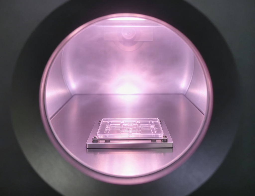
PDMS bonding with oxygen plasma is widely used to seal microfluidic chips, lab-on-a-chip devices, biomedical research components and precision fluidic structures. Plasma treatment changes the surface condition of PDMS so that it can bond directly to glass, silicon oxide or another activated PDMS layer without adding a conventional adhesive between the two surfaces.
This approach can help avoid adhesive thickness, residue and microchannel blockage. However, reliable PDMS plasma bonding depends on surface cleanliness, plasma gas, treatment power, chamber pressure, exposure time, sample loading and the delay between activation and contact.
This guide explains how PDMS plasma bonding works, how to develop a repeatable process, how to identify common bonding failures and how to choose a suitable plasma cleaner for PDMS bonding .
Polydimethylsiloxane, commonly known as PDMS, is a silicone-based elastomer frequently used in microfluidics and biomedical research. It is transparent, flexible, moldable and suitable for forming small channels, chambers, membranes and other microscale structures.
Once these structures have been formed, the patterned PDMS layer usually needs to be sealed against a flat substrate to create an enclosed fluid path. Common substrate combinations include:
Untreated PDMS normally creates only weak, reversible contact with these materials. Plasma bonding modifies the outermost surface of the substrates before they are brought into contact. Under suitable treatment and assembly conditions, this activated interface can form a strong and durable bond without a separate glue layer.
Native PDMS has a low-surface-energy, hydrophobic surface dominated by non-polar methyl groups. Water tends to form droplets rather than spread evenly, and the untreated material does not readily form strong chemical bonds with glass or another PDMS surface.
Directly pressing untreated layers together may create temporary contact, but the interface can separate during handling, fluid injection, pressure testing or long-term operation.
Common problems associated with untreated or poorly prepared PDMS include:
Plasma treatment addresses the surface-chemistry limitation rather than relying only on mechanical pressure. For a broader explanation, see how plasma surface activation improves bonding .
Inside a vacuum plasma chamber, oxygen, clean air or another selected process gas is energized to create a reactive plasma containing electrons, ions, radicals and excited molecules. These species interact with the outermost molecular layers of the material.
During oxygen plasma treatment, the surface methyl groups on PDMS are modified and oxygen-containing functional groups are introduced. This process can create silanol groups, represented as Si–OH, while increasing surface energy and improving wettability.
When two compatible activated surfaces are brought into sufficiently close contact, silanol groups at the interface can undergo condensation reactions and form Si–O–Si linkages. This interfacial reaction is the basis of direct PDMS-to-glass and PDMS-to-PDMS plasma bonding.
Important: plasma-induced hydrophilicity is not permanent. PDMS gradually undergoes hydrophobic recovery after treatment. The activated surfaces should therefore be aligned and contacted as soon as practical. A successfully formed bond may remain durable even though an exposed plasma-treated surface later becomes more hydrophobic.
Plasma activation, plasma cleaning and plasma etching serve different purposes. Learn more in Plasma Activation vs. Cleaning vs. Etching .
Plasma activation makes direct bonding possible without placing a conventional glue layer between compatible substrates. This can reduce the risk of adhesive residue, uneven bond-line thickness and accidental obstruction of small fluid channels.
Because plasma treatment primarily modifies the surface, it can be used for components containing microchannels, cavities, membranes and other delicate features. Treatment parameters and subsequent handling must still be validated for the actual structure.
Cold plasma treatment can modify the surface without heating the entire component to the temperatures associated with some thermal bonding methods. This makes it useful for heat-sensitive PDMS layers and hybrid assemblies, provided that power, exposure time and part temperature are controlled.
A vacuum plasma cleaner can surround exposed samples with reactive plasma, supporting treatment of complete bonding surfaces and multiple parts within a chamber. Fixture design, sample spacing and loading position should remain consistent to achieve repeatable results.
Compact systems can support laboratory development and small batches, while larger vacuum chambers, multi-level carriers, recipe control and automated handling can support pilot or industrial production.
| Bonding Combination | Typical Applications | Main Advantages | Important Considerations |
|---|---|---|---|
| PDMS to Glass | Microfluidic chips, diagnostic cartridges and optical observation devices | Transparent interface and dimensionally stable supporting substrate | Glass cleanliness, flatness, dust control and rapid contact after activation |
| PDMS to PDMS | Multilayer chips, flexible membranes, valves and pneumatic structures | Maintains an all-elastomer structure without adding an adhesive layer | PDMS cure condition, alignment, surface flatness and activation of both layers |
| PDMS to Silicon or SiO2 | MEMS, sensors, wafer-based devices and hybrid electronic assemblies | Integration of PDMS fluidic structures with rigid silicon components | Wafer coatings, contamination, embedded devices and downstream temperature limits |
PDMS-to-glass bonding is commonly used to seal molded microchannels while maintaining optical access through the glass substrate. Both the PDMS and glass surfaces are normally cleaned and activated before contact.
Dust, fingerprints, oils and residual cleaning chemicals can prevent intimate contact. Even a small particle can create an unbonded region that is much larger than the particle itself. Clean handling and controlled storage are therefore essential.
PDMS-to-PDMS bonding is used for multilayer devices containing channels, flexible membranes, pneumatic valves or stacked fluidic structures. Both PDMS surfaces generally require activation before alignment.
Cure ratio, curing time, storage conditions and surface contamination may influence bonding performance. Thin PDMS layers should be handled carefully to avoid stretching, folding or channel collapse during assembly.
Bonding PDMS to silicon or an oxidized silicon surface can support the integration of microfluidic structures with sensors, electrodes, MEMS components and wafer-level devices. The actual process must account for surface coatings, topography, electrical structures and other materials already present on the wafer.
Confirm that the PDMS has been mixed and cured according to the selected material formulation. Incomplete curing, surface bloom or uncured residue can interfere with activation and reduce bond consistency.
Inspect the bonding surface for dust, fingerprints, scratches, deformation and visible contamination. Avoid touching the bonding area with bare hands.
Remove particles, oils and processing residues using a cleaning method compatible with the PDMS and the second substrate. After wet cleaning, make sure the parts are fully dry before loading them into the plasma chamber.
Surface cleaning and surface activation are related but not identical. For more detail, read the guide to plasma cleaning technology .
Position the PDMS and matching substrate so that the intended bonding surfaces are exposed to the plasma. Do not stack parts in a way that shields the treatment area.
For batch production, standardize the carrier, number of samples, spacing, layer position and orientation. A recipe validated with one loading configuration may not provide the same result after the chamber is filled differently.
Oxygen is widely used for direct PDMS bonding because it supports the formation of oxygen-containing functional groups. Clean air may also be evaluated where the equipment and process requirements allow it.
Argon can assist with physical surface cleaning, but an argon-only process does not provide the same oxygen-rich surface chemistry. Nitrogen processes may be useful for other functionalization objectives and should not automatically be treated as equivalent to an oxygen bonding recipe.
The primary variables normally include:
The objective is to apply enough plasma dose to activate the surfaces without unnecessarily increasing oxidation, surface roughness or damage to sensitive structures.
Longer treatment does not automatically produce a stronger bond. Insufficient exposure may leave the surface under-activated, while excessive power or treatment time may alter the surface and reduce process performance.
After treatment, vent the chamber and move the samples to the bonding step without unnecessary delay. Keep the activated surfaces protected from dust, handling and airborne contamination.
Align the channel pattern and substrate carefully before allowing full contact. Starting from one edge or one controlled contact point can help the contact front spread across the interface while reducing trapped air.
Apply only the gentle and uniform pressure required to establish contact. Excessive pressure may deform thin membranes, move aligned features or collapse unsupported microchannels.
Depending on the materials and required bond performance, the assembly may be held at room temperature or subjected to a moderate post-bond bake. Any heating stage must be validated against the PDMS geometry, coatings, embedded components and downstream use.
Examine the interface for particles, bubbles, incomplete contact, misalignment and channel deformation. Functional parts should undergo a leak, pressure or flow test that reflects their expected operating conditions.
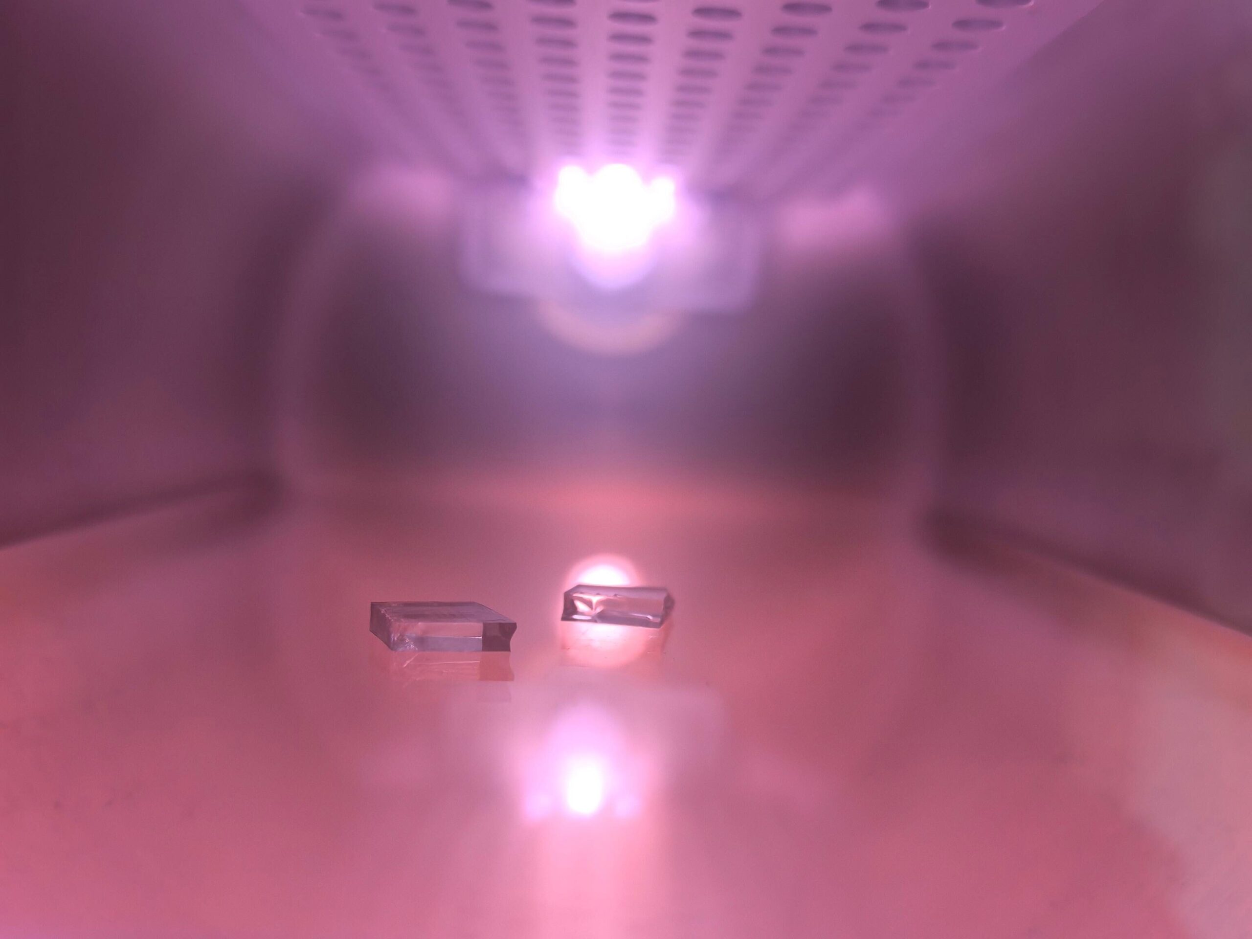
| Process Variable | Why It Matters | Recommended Control Method |
|---|---|---|
| Surface cleanliness | Particles and organic films prevent direct contact between the substrates | Standardize cleaning, drying, gloves, storage and transfer procedures |
| Process gas | Gas chemistry determines the reactive species formed in the plasma | Evaluate oxygen or clean air using the actual PDMS and substrate |
| Plasma power | Influences activation rate and the risk of excessive surface modification | Identify a stable operating window instead of using maximum power by default |
| Treatment time | Insufficient and excessive treatment may both reduce performance | Test multiple exposure levels while keeping other variables constant |
| Chamber pressure | Affects plasma stability, density and energy distribution | Monitor vacuum performance and use repeatable pressure settings |
| Sample loading | Part position and chamber loading can affect treatment uniformity | Use consistent trays, spacing, orientation and batch quantity |
| Bonding delay | Hydrophobic recovery and contamination begin after treatment | Align and contact the activated surfaces as soon as practical |
| Assembly pressure | Excessive force may deform membranes or collapse channels | Apply controlled, uniform and application-appropriate pressure |
| Post-bond heating | May accelerate interfacial bond development but can affect sensitive parts | Validate temperature and time against the complete device design |
Possible causes include:
Begin by checking cleanliness, vacuum stability and the delay between treatment and contact. Change only one variable at a time during troubleshooting so that the actual cause can be identified.
Partial bonding is frequently associated with particles, surface curvature, poor flatness, trapped air, fixture shadowing or non-uniform plasma exposure.
A localized unbonded region surrounding one point often indicates contamination. A repeated pattern across several parts may indicate a loading, electrode or plasma uniformity issue.
A visually complete interface does not necessarily confirm adequate pressure resistance. Leakage may result from weak activation around channel edges, contamination, port damage, mechanical stress from tubing or insufficient contact near the fluid path.
Test the completed device under a defined pressure, flow rate and holding time rather than relying only on visual inspection.
Channel deformation may be caused by excessive assembly pressure, thin unsupported PDMS, unsuitable heating conditions or stretching during alignment.
Reduce unnecessary mechanical force, use appropriate support fixtures and validate the complete bonding workflow with the smallest and most delicate structures in the device.
Batch variation may be related to changes in:
Recipe storage, recorded process data, standardized carriers and routine chamber maintenance can improve repeatability.
Water contact angle measurement can confirm whether plasma treatment has changed the PDMS surface from strongly hydrophobic toward more hydrophilic behavior. A lower contact angle generally indicates improved wetting and successful surface activation.
Contact angle should not be the only acceptance criterion. A surface may show improved wettability but still fail to bond because of particles, damage, delayed contact or an incompatible substrate.
When clean activated surfaces touch, the contact front should normally spread across the interface. Interrupted or irregular spreading may indicate dust, trapped air, poor flatness or non-uniform activation.
Introduce a suitable test fluid or gas at a controlled pressure and inspect the channel edges, ports and bonded interface. The test pressure and duration should reflect the device’s intended operating conditions.
Mechanical tests can compare different plasma recipes during process development. Sample dimensions, loading direction, cure condition and test speed should remain consistent so that results are comparable.
Optical microscopy can reveal particles, bubbles, alignment errors and channel deformation. Advanced analytical methods such as XPS may be used during research or process development to evaluate changes in surface chemistry.
Plasma bonding can seal molded channels used for fluid transport, mixing, separation, droplet generation and other microscale operations.
Multilayer PDMS structures may combine channels, chambers, membranes and pneumatic control features within a compact analytical platform.
PDMS bonding may support cell-culture chips, organ-on-chip research platforms, diagnostic research cartridges and other laboratory fluidic devices. Final material compatibility and biological performance must be validated for the intended use.
PDMS structures can be bonded to silicon, glass and sensor substrates for hybrid devices that combine fluid control with electrical, optical or mechanical sensing functions.
Plasma treatment may also be used for small cavities, optical assemblies, flexible membranes and other precision components where adhesive thickness or residue could interfere with device performance.
Explore additional plasma treatment applications for medical and biomedical manufacturing .
A suitable PDMS plasma bonding machine should provide controlled and repeatable surface activation rather than simply generating visible plasma. Equipment selection should be based on the substrate size, process gas, chamber loading, required uniformity and production volume.
The chamber must accommodate the largest PDMS and matching substrate while allowing the active surfaces to remain exposed. Consider tray dimensions, number of layers and spacing between parts rather than relying only on the nominal chamber volume.
Uniform treatment is especially important for large chips and multi-part batches. Evaluate results at several positions across the usable loading area rather than measuring only one sample near the center of the chamber.
For oxygen plasma PDMS bonding, the gas path, chamber and plasma source must be compatible with the selected gas. Independent gas channels can also support process development with oxygen, air, argon or other approved gases.
Adjustable parameters make it possible to identify a process window for different PDMS thicknesses, channel geometries, substrates and batch sizes. Recipe storage can reduce operator variation after the process has been validated.
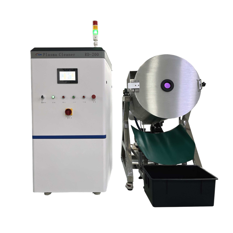
A compact benchtop chamber may be appropriate for R&D and small batches. Larger chambers, multi-level loading and automated transfer may be needed when the process moves into pilot or industrial production.
Stable vacuum performance, gas-flow control, plasma output and chamber cleanliness all affect bonding repeatability. Select equipment that allows operators to monitor the important process variables and perform routine maintenance.
The GD-10RF compact RF oxygen plasma cleaner is designed for laboratory and small-batch vacuum plasma processing. It uses a 13.56 MHz RF plasma source with adjustable output up to 300 W, a 10 L chamber, PLC touchscreen control and two gas channels.
The system supports oxygen, air, argon and nitrogen process gases, allowing users to develop controlled cleaning and activation recipes. Suitability for a specific PDMS device should be confirmed through sample trials using the actual materials and bonding requirements.
Higher-volume production may require a larger vacuum chamber, custom carriers, multi-level loading, automated door operation, recipe management or integration with alignment and material-handling equipment.
Fari Plasma provides equipment matching and plasma system customization for production lines requiring custom chamber dimensions, fixtures, controls or automation interfaces.
Selecting a plasma cleaner requires more than matching the chamber size. The plasma process should be evaluated using the actual PDMS formulation, substrate, bonding area, channel design and required production throughput.
Provide the following information when requesting a process evaluation:
Contact Fari Plasma to discuss a vacuum plasma system and process configuration for your PDMS bonding application.
Yes. Oxygen or clean-air plasma can activate clean PDMS and glass surfaces so that a direct bond forms after contact. Final bond performance depends on cleanliness, plasma settings, surface compatibility and the delay before assembly.
No. The exposed PDMS surface gradually undergoes hydrophobic recovery after treatment. Activated surfaces should be bonded promptly. A successfully formed interfacial bond can remain durable even though untreated exposed areas later become more hydrophobic.
The substrates should be aligned and contacted as soon as practical. The acceptable bonding window depends on the plasma recipe, material formulation, storage environment and required bond strength.
Oxygen is commonly used because it supports the formation of oxygen-containing surface groups. Clean air may also be evaluated. Gas selection and treatment parameters should be confirmed with the actual PDMS and substrate.
A controlled low-temperature plasma process can activate PDMS without heating the entire part to a high temperature. Excessive power or exposure can still change surface properties, while excessive assembly pressure can deform thin channels. The process must be validated for the specific device.
Common causes include particles, fingerprints, residual solvent, incomplete PDMS curing, insufficient or excessive plasma exposure, unstable chamber pressure, non-uniform treatment, delayed contact or an incompatible surface coating.
Common methods include contact angle measurement, visual contact-front inspection, leak testing, burst-pressure testing, peel testing, shear testing and microscopy. The selected acceptance test should reflect the intended operating conditions.
Yes. Production systems may use recipe control, custom carriers, automated loading, chamber handling and integration with alignment or transfer equipment. The automation design depends on the part geometry, batch size and required cycle time.




English

Spanish
Rogatus ad ultimum admissusque in consistorium ambage nulla praegressa inconsiderate